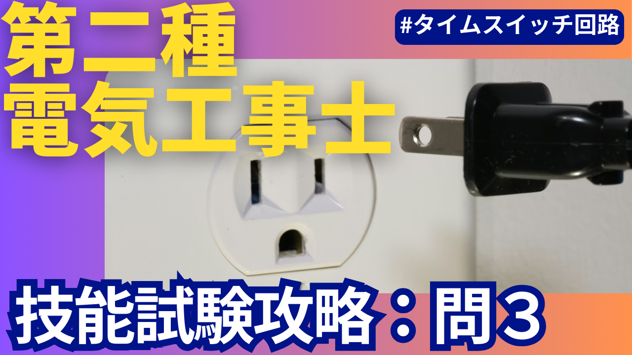
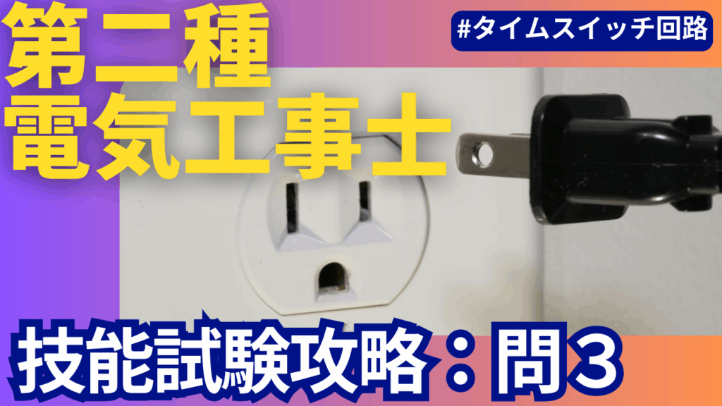
Tips for installing a time switch and an outlet with a grounding electrode in one go [Part 3 of the series]
Hello everyone, this is DIY Renova.
In this article, we will focus on "Published Question 3" of the Type 2 Electrician Skills Examination, and summarize everything from the concept of wiring diagrams to the practical procedure and defect checking.
If you're wondering "How much renovation or remodeling can I actually do on my own home?" or "Where should I even start?", please visit this page. If you're looking to learn more about specific renovation processes or construction details, don't miss this page as well!
Information on updates to this website will be delivered to you once a month.NewsletterIf you are interested, please register.
Basic information
- Main exam number: Second class electrician skill test published question 3
- What is the theme of this exam number?
- Correct wiring of time switch
- Routing of electrical outlets with grounding terminals and grounding wires (earth)
- Branching power and loads using terminal blocks
- How to use "Ring Sleeve" and "Plug-in Connector" for left and right joint boxes Denkiya Peko
According to Mr. Peko the Electrician's explanation, the difficulty level of this published problem 3 is ``3 out of 5''. While the wiring inside the joint box itself is not that complicated, the time switch, terminal block, and grounded outlet are all involved, making it easy to make wiring mistakes or forget to connect the ground wire. Electrician Peko
On the Gamidenki channel, the concept of the time switch part and forgetting to remove the grounding wire from an outlet with a grounding terminal are highlighted as typical defects. (Gamidenki channel)
Tools needed for this exam
Here, we will organize the minimum and easy-to-have tools for the actual exam. Please read using your favorite tools.
- VVF stripper (VA stripper)
- Standard tool for VVF1.6mm. Prepare something that can quickly strip the coating and cut the core wire.
- For example, HOZAN VA strippers are also popular with prospective students. (Electricist Peco)
- This is a good time to search for ``VVF stripper 1.6mm'' on Amazon or Yahoo Shopping and choose the one that suits your hands.
- Eccentric pliers (pliers)
- Essential for positioning ring sleeves, twisting copper wire, and fine bending.
- Crimping tool (for ring sleeve)
- Crimping pliers from Mirai Kogyo, Hozan, etc. that are compatible with "small" and "medium" sleeves.
- If the crimp mark (such as "small" or "medium") is not placed firmly, it will be defective.
- Driver (plus/minus)
- Used for tightening screws on time switches, terminal blocks, outlets with grounding terminals, ceiling hooks, etc.
- We recommend a type with plenty of grip to prevent your hand from slipping when tightening the screws after inserting the wires.
- Scale (measure) or graduated tool
- A must-have item for quickly measuring specified dimensions such as 100mm and 150mm.
- nipper
- Convenient for finely adjusting the length of IV wires around time switches and terminal blocks.
- Electricity detection driver (optional)
- Although the actual energization test will not be performed at the test venue, it will be useful for self-practice and when checking voltage in the workplace, so it is a good idea to get used to it.
On the actual question paper, the ``distance between cores'' of each cable is indicated in dimensions such as 100 mm, 150 mm, and 200 mm. On the other hand, the idea is to cut the cable by adding the length that will fit inside the device or the length required for the joint (Electrical Shop Peko, 2023).
How to use HOZAN “Pass Multi-Tool”
Noriyama's passing multi-tool (a type that combines stripper, pliers, and scale functions) is also very useful in Publication Question 3.
- Dimensions
- Quickly mark "100mm" and "150mm" with the scale engraved on the tool.
- VVF exterior removal
- Peel off 1.6mm VVF at the specified length at once. Since there is less variation, the inside of the joint box will fit neatly.
- Making a loop of core wire
- We can mass-produce rings of the same size that fit into screw-fastening parts of lamp receptacles and terminal blocks.
- Sleeve alignment
- The clamp part of the tool is also useful when adjusting the sleeve position after aligning the core wires.
It is a good time to have a ``passing multi-tool'' with you at the tool selection stage before the exam, as it will help stabilize your work flow from the practice stage and reduce the chance of making mistakes.
Materials to be prepared for this exam
Here, we will organize the materials assuming the structure of a typical publication problem 3. In reality, be sure to give priority to the "List of supplied materials" and "Construction conditions" on the question paper distributed by the test center. (Hozan)
Cables
- VVF 1.6mm 2 cores (black/white)
- Used for main lines and branches such as from power supply to terminal block, terminal block to time switch, time switch to load, etc.
- 1.6mm² copper wire is a standard thickness used in household branch circuits up to 16-20A (there is an engineering reason that the larger the cross-sectional area of the copper, the higher the allowable current and the less heat generated).
- VVF 1.6mm 3-core (black/white/red)
- Used for parts that require multi-wire connections, such as signal lines from a switch to a terminal block, or from a terminal block to a time switch.
- IV 1.6mm (single wire)
- It may be used inside the terminal block of a time switch or for routing the ground wire.
- The covering color is black, white, green (ground), etc., depending on the construction conditions.
Instruments (typical examples)
- Time switch (for board embedding)
- The internal wiring diagram shows "power supply," "load," "ground," etc., and the wiring method is specified according to the construction conditions. (Electricist Peco)
- Grounded outlet
- A type with a ground terminal (marked) and a ground electrode (round hole). Gamidenki Channel introduces this forgetting to connect the ground wire as a typical defect. (Gamidenki channel)
- terminal block
- Used to neatly separate the power supply side and load side. The screw type is common, and the core wire is inserted straight and tightened securely.
- Lighting equipment such as hanging ceilings and lamp receptacles
- Continuous mounting frame
- In published problem 3, instructions are given to use the multiple-use mounting frame provided as an outlet. (Electricist Peco)
- Please note that if you forget to use it, it may be considered "unfinished".
connection member
- Ring sleeve (small/medium)
- Specified in the construction conditions to be used to connect the left side joint box. (Electricist Peco)
- pluggable connector
- Specified for use on the right joint box. (Electricist Peco)
If you do not comply with the specifications of "Part A = Ring Sleeve" and "Part B = Plug-in Connector," you will be immediately disqualified as a violation of the construction conditions, so as soon as you open the problem, write "A = Ring" and "B = Plug-in Connector" in large letters with a marker or pencil. (Electricist Peco)
Main flow (specialized in time switches and outlets with grounding electrodes)
From here on, I will explain the general flow of completing Publication Question 3 in 40 minutes, and where you can use a passing multi-tool to make it easier, organized on a time axis.
0-5 minutes: Confirmation of question paper and construction conditions
- Quickly read the wiring diagram and construction conditions
- How to wire a time switch
- How to connect A/B joints (ring sleeve/plug connector)
- Specify the color of the ground wire (white for the installation side, green for the ground wire, etc.) (Electric Shop Peco)
- Check the internal wiring diagram of the time switch
- Carefully read the terminal displays such as "Power L", "Power N", "Load", and "Ground" once.
- In the HOZAN video, the relationship between switch operation and load lighting is deciphered from the internal wiring diagram. (Hozan)
- If you use the scale of a passed multi-tool to write down approximate dimensions on the wiring diagram (for example, 150 mm between power supply, terminal block, and time switch, 250 mm between appliances, etc.), later cutting to dimensions will be smoother.
5-10 minutes: Creating a double line diagram
Electrician Peko suggests a fairly aggressive time allocation, saying, ``You should only have about 30 seconds to draw a double-track diagram,'' but you can use as little as 5 minutes at first. (Electricist Peco)
The basic rules are:
- copy the equipment
- Place the power supply, joint box, terminal block, time switch, lighting equipment, and grounded outlet on the whiteboard or in the margin of the question paper according to the wiring diagram. (Hozan)
- Distribute N (white line) to all loads
- Connect the white wire from the power supply N via the joint box to the N terminal required by the lighting equipment, outlet, and time switch.
- It is also important to always route through the joint box without taking diagonal shortcuts. (Gamidenki channel)
- Distribute L (black wire) to switches
- Branch the black wire from the power supply L to the time switch input side and the necessary switch/outlet via the joint box and terminal block.
- You can reduce the number of cables by connecting branches with jumpers. (Gamidenki channel)
- From the load side of the time switch to the lamp
- Extend the black wire (or red wire) from the "load terminal" of the time switch to the corresponding light.
- At this time, it will be less confusing if you draw a double-line diagram with the image of treating the time switch as ``one special switch.''
- Connect the ground wire (green) to a grounded outlet
- Draw a grounding wire from the power supply side or terminal block, and draw the route to connect it to the grounding terminal of the grounded outlet on a double-line diagram.
- Gamidenki Channel also explains that failure to fill in or connect the ground wire is a typical defect. (Gamidenki channel)
If you follow these steps carefully, you will greatly reduce the risk of getting lost during the practical work later on.
How to draw wiring diagrams and things to be careful about
In this chapter, we will summarize the key points that are unique to Publication Problem 3, such as ``time switches'', ``grounded outlets'', and ``terminal blocks'' without making any mistakes when transferring them to a double-track diagram.
Disassemble and think about the time switch as a "switch + terminal block"
A time switch has internal components such as a "power input", "load output", "clock part", and "ground terminal", so looking at the internal wiring diagram it seems complicated. Therefore, when drawing a double-line diagram, it is easier to understand by simplifying it as follows.
- Draw it as a "small terminal block" where the power supply L/N is inserted.
- Draw it as a "terminal block with a switch" that goes out to the load.
HOZAN's video also explains how it works as a switch, looking at the internal wiring diagram and saying, ``If you attach a crossover wire, it lights up like this.'' (Hozan)
In other words, at the double-line diagram stage, the trick is to only be aware of the flow of the lines, ``power supplies L and N enter here and output to the load here,'' and not to worry too much about the internal structure.
Symbol of outlet with grounding terminal and grounding wire
A grounded outlet has a different symbol and structure than a simple two-prong outlet.
- “Grounding electrode (round hole)” and “grounding terminal” are clearly indicated on the symbol.
- Be sure to connect the ground wire (green) to the ground terminal
- Connect N (white wire) to the ground side pole as usual.
The Gamidenki channel's explanation also emphasizes that you must always connect the wires to the installation marks. (Gamidenki channel)
On the double-track diagram, add a "ground wire" near the outlet symbol to clearly indicate that the green wire comes from the joint box, so you won't forget the ground wire during practical training.
Distinguishing A/B joints and connection methods
In published problem 3, the connection method is different between the left joint box (part A) and the right joint box (part B). (Electricist Peco)
- Part A: Connection by ring sleeve
- Part B: Connection via plug-in connector
On the double-track diagram, write a small note for yourself such as "R (Ring)" for part A and "C (Connector)" for part B, so you don't get confused during the practical exercise.
How to proceed with practical skills and take a breather
From here, we'll move on to how to actually move your hands. We will also take a look at the specific uses of tools, including passing multi-tools.
Step 1: Cutting to size (approximately 10-15 minutes)
- While looking at the multi-line diagram, make a list of the number and length of cables required.
- Where the construction conditions specify ``150mm,'' you can make the work more stable by cutting the sections uniformly to 290mm, like Mr. Peko, an electrician, will do. (Electricist Peco)
- Mark the cable using the scale of the passed multi-tool → cut it all at once with the stripper section.
The engineering point here is that "it will not become a defect unless it is less than 50% of the specified dimension." (Electricist Peco)
For example, if the length is 60 to 120 mm compared to the specified 100 mm, it is acceptable, but if it is too short, it will be weak against tension, so it is best to leave some margin.
Step 2: Stripping the coating and preparing the core wire (about 10 minutes)
- Strip the outer sheath and core wire about 100mm from the cable going into the joint box, and about 50mm from the equipment side. (Electricist Peco)
- Strip the core wire that is inserted into the time switch, terminal block, or outlet terminal straight to a length of approximately 10 to 12 mm to ensure sufficient contact area with the screw terminal.
- To make sure that the core wire you insert into the lamp receptacle is bent in advance into a "loop shape" like Peko did, and wrapped around it in the direction of rotation of the screw. (Electricist Peco)
At this time, if you mass-produce rings of the same diameter using the ring-making function of a passed multi-tool or the tapered part, it will look nicer and improve work efficiency.
Step 3: Wiring to the equipment (time switch, terminal block, outlet) (approximately 10 to 15 minutes)
- terminal block
- Connect the power supply side (primary side) and load side (secondary side) as shown in the double-line diagram.
- Group the black wires (L) together at the same pole, and do the same for the white lines (N).
- time switch
- Follow the internal wiring diagram you saw beforehand and connect the "power supply L", "power supply N", "load", and "ground" without making any mistakes. (Electricist Peco)
- When inserting into the screw terminal, adjust the core wire so that about 2 to 3 mm is visible, but do not expose more than 5 mm (the longer it is exposed, the greater the risk of shorting).
- Grounded outlet
- Connect the white wire to the ground side pole and the black wire to the non-ground side pole.
- Be sure to connect the green ground wire to the ground terminal. If you forget this point, you will immediately be at fault. (Gamidenki channel)
- Securely secure the outlet to the continuous mounting frame. If you do not use this, it will be treated as incomplete. (Electricist Peco)
- Lighting equipment (hook ceiling, lamp receptacle)
- Make sure to connect black and white according to the double line diagram.
- Make sure to wrap the loop in the direction you are tightening the screw so that the more you tighten it, the more it digs in.
Step 4: Connection with joint box (about 5-8 minutes)
- Part A (left side): Ring sleeve
- Align the core wires of the same group, adjust the length using a qualified multi-tool, insert the ring sleeve, and use a crimping tool to crimp at the specified positions "small" and "medium" until the mark clicks. (Hozan)
- Part B (right side): Plug-in connector
- Arrange the core wires straight and insert them in the specified number.
- Be sure to visually check that the core wire is inserted all the way and that the tip of the copper wire is visible through the transparent window.
If A and B are reversed, it will be a violation of the construction conditions and you will be out immediately, so all you have to do is be careful enough to actually write "A = ring" and "B = insert" on the joint box with a pencil before connecting. (Electricist Peco)
Step 5: Final check and time allocation (5 minutes remaining)
- Have you forgotten to tighten the screws on each device?
- Is the ground wire always connected to the ground terminal?
- Does the time switch terminal display match the wiring?
- Are the parts used for A and B joints correct?
HOZAN's video also shows how to temporarily add a crossover wire at the final stage and check that it is lit to confirm that the operation matches the internal wiring diagram. (Hozan)
Items to check for defects/overlooks (particularly common in Publication Question 3)
Finally, we will summarize the flaws that are particularly likely to occur in Publication Question 3 and check points. Make this your own checklist and go through it one by one after completing your work.
- Time switch wiring error
- Mix up power supply L and load terminals
- I forgot to add N so it doesn't work.
- There is no ground wire in the ground terminal.
→ Countermeasure: Carefully trace the internal wiring diagram and construction conditions again after wiring.
- Forgetting the grounding wire of the outlet with a grounding terminal
- green wire is not connected anywhere
- Mistaking the white line and the green line
→ Countermeasure: Check out loud whether there are three plugs (black, white, and green) around the electrical outlets.
- Violation of A/B joint connection method
- A plug-in connector is used on the A side.
- I end up using a ring sleeve on the B side.
→ Countermeasure: Write "A=Ring" and "B=Plug" in pencil on the joint box and visually check after connecting. (Electricist Peco)
- Poor crimping of ring sleeve
- There is no crimp mark
- The crimping position is different from the specified one, such as "small" or "medium".
→ Countermeasure: After crimping, be sure to visually check the markings and gently pull the sleeve to check if it comes off.
- Inadequacies in stripping dimensions and copper wire exposure
- Long exposed copper wires inside the joint box
- The coating gets caught in the device terminal, resulting in poor contact.
→ Countermeasure: Use a pass multi-tool or a stripper gauge to repeatedly practice stripping both the outer and core wires to a certain length.
- Forgetting to attach the continuous mounting frame
- Fixing the outlet without a frame
→ Countermeasure: When arranging the equipment on the board, make it a habit to always install it on the frame first. (Electricist Peco)
- Fixing the outlet without a frame
Finally (how to connect to the next practice)
Published problem 3 is a step more advanced than published problems 1 and 2, but it is a theme that allows you to thoroughly practice the ``combinations that often come up in practice'' such as a time switch, a grounded outlet, and a terminal block.
- Time switch = "special switch"
- Outlet with a grounding terminal = “An outlet through which the grounding wire must be passed”
- Terminal block = "A place where power supplies and loads are organized and branched out"
Once you have this image in mind, you will be able to apply it to other public issues and practical work.
If you search for practice equipment on Amazon or Yahoo Shopping, etc., you can search for ``Class 2 electrician skill test practice set'', ``time switch for practice'', or ``outlet with grounding electrode for practice'', and you will also find kits containing the necessary equipment. While reading this article, try building and breaking down the same problem several times at home to memorize the steps.
If you're wondering "How much renovation or remodeling can I actually do on my own home?" or "Where should I even start?", please visit this page. If you're looking to learn more about specific renovation processes or construction details, don't miss this page as well!
Information on updates to this website will be delivered to you once a month.NewsletterIf you are interested, please register.
Reference videos/reference materials
- Denkiya Peko “2023 Candidate Question Number 3 Explanation Video” Denkiya Peko
- Gamidenki channel “Publication problem 3: Explanation of time switches and outlets with grounding electrodes” Gamidenki channel
- HOZAN “Class 2 Electrician Skills Exam Publication Question 3 Explanation Video” Hozan
Next time, we are planning an article on the theme of Publication Problem 4. Following the time switch, another special device will appear, so make sure to make this time's content your own before reading on.
Leave a Reply
You must be logged in to post a comment.