Actually, I am also learning by summarizing things like this lol
If you're wondering "How much renovation or remodeling can I actually do on my own home?" or "Where should I even start?", please visit this page. If you're looking to learn more about specific renovation processes or construction details, don't miss this page as well!
Information on updates to this website will be delivered to you once a month.NewsletterIf you are interested, please register.
So, here you go.
Basic information
- Exam time: 40 minutes (common for candidate questions)
- Equipment configuration: lamp receptacle (or hanging ceiling) + lighting fixture + EET (outlet with grounding terminal) + grounding electrode
- Cable used: VVF2.0-2 core, E wire 1.6mm, etc. (may be finely adjusted depending on the year, be sure to check the construction conditions)
- Connection method: Mainly a combination of "white crimp" using a ring sleeve (small sleeve) and a plug-in connector (Gamidenki channel)
- What is the theme of this exam number?
- "Correct wiring and grounding work for EET outlets (outlets with grounding terminal + grounding terminal)"
- "Construction of cutting VVF2.0-2 core cable once in the middle and branching" (Gamidenki channel)
- "Reliable crimping using small ring sleeve (white)" (Gamidenki channel)
The circuit itself for No. 9 is not that complicated, but the test is whether you can carefully handle three points at once: ``EET polarity,'' ``white crimp,'' and ``cutting the 2.0 mm cable midway.''
Tools needed for this exam
The basic tools are the same as for other problems, but since most of the problems involve hard white crimping and 2.0mm cable processing, it will be much easier if you have tools that can supplement your grip strength.
- Crimping tool (for ring sleeve)
- Something that can reliably crush small (white) objects. The longer grip type makes it easier to apply force.
- VVF stripper (1.6mm/2.0mm compatible)
- For example, HOZAN's VVF stripper P-929 is compatible with both 1.6/2.0 mm 2-core and 3-core outer and core wire stripping, and can cut and strip the coating in one action, which is quite effective in reducing testing time (according to manufacturer specifications).Amazon+1
- By placing product links from Amazon and Yahoo! Shopping around this part of this article, it will be easier for readers to get the tools they need.
- Nippers/pliers (for stripping and cutting when not using a VVF stripper)
- Driver (+/-)
- major (or scale)
- Utility knife (if necessary)
- Electrician knife (assistance if you don't have a stripper)
- Pencil/Eraser (for double-track diagrams)
In addition to this,
- HOZAN “Pass Multi-Tool” DK-200
- A small tool included in HOZAN's skill test set, which includes a scale with graduations, a blade for lightly scraping coatings, and protrusions that can be used for chamfering, etc.
- For published question 9, it is useful to use it as a simple ruler to measure the ``10cm sheath peeling'' and ``12mm strip length'' described later.
Materials to be prepared for this exam
Although the detailed length changes depending on the year, the structure is generally fixed. In the diagram published by the test center (R7 candidate question), No. 9 has the following structure.Exam Information Center
- VVF2.0-2 core cable
- Power supply ~ joint box
- Joint box ~ lighting
- Joint box ~ EET outlet
- E line (IV1.6mm green, etc.)
- From the ground terminal to the ground terminal of the EET outlet
- Lamp receptacle or hook ceiling (R symbol)
- Another lighting fixture (lower part of the diagram)
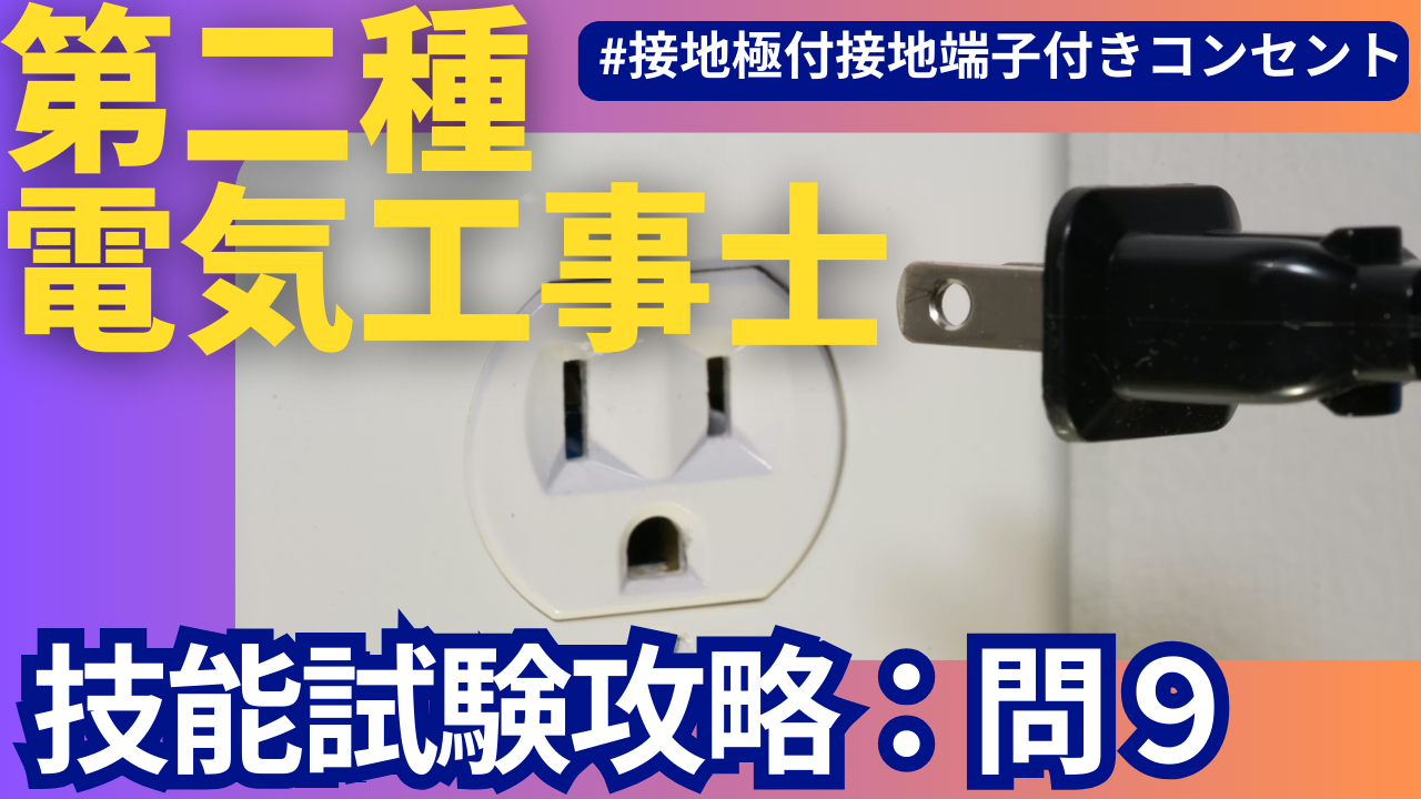
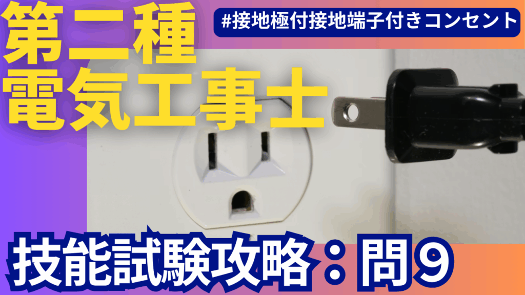
- EET outlet (grounding terminal + outlet with grounding terminal) (Gamidenki channel)
- Required number of ring sleeves (small/medium), plug connectors
If you want to gather the materials yourself for practice, you can buy HOZAN's wire rod set or electrician test set, which will make it easier because it comes with a set of VVF2.0-2 core, E wire, and ring sleeve for each problem.
On the actual question paper, the ``distance between cores'' of each cable is indicated in dimensions such as 100 mm, 150 mm, and 200 mm. On the other hand, the idea is to cut the cable by adding the length that will fit inside the device or the length required for the joint (Electrical Shop Peko, 2023).
Main flow
The flow of Publication Question 9 will be stable if you roughly follow the steps below.
- Confirmation of question paper and construction conditions
- Checking and cutting out equipment and cable length
- draw a double line diagram
- Terminal processing for each device (including EET)
- Temporary connection/crimping mark on joint box
- Crimp with ring sleeve white
- Connection of ground wire/connection to EET
- Final confirmation of continuity image and defect check
Let's take a closer look at each.
1. Check the question paper and construction conditions
First, before the 40-minute "construction time" begins, we take the time to check the supplied materials and carefully read the construction conditions on the question paper. HOZAN's commentary repeatedly warns, ``There may be differences in dimensions and conditions between candidate questions and past questions, so be sure to look at the actual construction conditions before practicing.'' (Hozan)
Especially in No.9,
- Type of EET outlet (recessed or exposed)
- Grounding wire route (E pole → EET only, or shared with other equipment)
- VVF2.0-2 core cable length distribution
Let's check.
2. Checking and cutting the cable length
Gamidenki's explanation states that ``Published problem 9 is characterized by cutting a 2.0 mm two-core cable once in the middle and branching it out for EET.'' (Gamidenki channel)
Typical pattern:
- From power supply to joint box VVF2.0-2 core (1 core)
- From joint box to lighting VVF2.0-2 cores
- From joint box to EET VVF2.0-2 cores
The supplied 2.0-2 core cable is the exact length required, or slightly longer. Measure the length with a tape measure, including the ``parts omitted for construction'' written in the construction conditions, and then cut.
Here, it is convenient to use HOZAN's passing multi-tool as a scale of "10cm" and "100mm". If you use a multi-tool to mark the 10cm sheath stripping and the length of the core wire to take out from the box, you will reduce variations in length and get a nice finish (in the explanation of the HOZAN wire set, it is recommended to manage the sheath length and strip length with a pass gauge or multi-tool).
3. How to draw wiring diagrams and things to be careful about
3-1. Basic structure of double-line diagram
There are three points to note about the double-track diagram in No.9:
- From power supply (white/black) to joint box
- From the joint box to the two lights (white is common, black is according to the instructions from the switch side)
- From the joint box to the EET outlet (white wire is the "W" terminal, black wire is the opposite side) (Gamidenki channel)
In particular, the EET part has a "W" mark on the back of the outlet, and the manufacturer specifies that the white wire should be connected here (this is also emphasized in the video explanation). (Gamidenki channel)
3-2. Assignment of conductor colors
Gamidenki's video introduces the steps to color code using the following rules. (Hozan)
- The "neutral wire" that goes from the power supply to each appliance must be a white wire.
- Assign the remaining side as a black wire (or red wire) to the switch or load side
- Don't forget to write down the white wire of the power supply that connects to the outlet (this is where it often comes off)
If you color the multi-line diagram according to this rule, you can see at a glance where the white lines connect and reduce wiring errors.
3-3. Writing crimp marks
At the joint part of the double-track diagram, write marks such as "C", "Round", "Medium", and "Small" to distinguish whether it is a ring sleeve or a plug-in connector. (Hozan)
At this time,
- 2.0mm x 2 cores 1 piece + 1.6mm 1 piece → 3 pieces in terms of number of fibers → Small sleeve (white)
- 2.0mm x 2 cores 2 + 1.6mm 1 → Equivalent to 4.6 cores → Middle sleeve (red)
As in, the cross-sectional area ratio (2.0mm² ≒ 3.14mm², 1.6mm² ≒ If you keep in mind that 2.01mm²) is roughly considered as ``2.0 = approximately 1.5 times 1.6'' to convert the number of fibers, it will be easier to judge without having to memorize the table (the actual crimping table is determined by each manufacturer, but in the skill test, small, medium, and large sleeves are selected based on this ``converted number of fibers table'').
How to proceed with practical skills and take a breather
From here on, I will explain the steps to actually move your hands, including where to take a break.
Step 1: Terminal processing to the equipment (take a break here)
- Strip the sheath of each cable by 10cm
- You can save time by cutting the exterior with a VVF stripper and removing the sheath just by holding the handle.
- Strip 12mm of the core wire coating
- Many EET outlets have a 12mm strip gauge, so peel them accordingly. Gamidenki's commentary also recommends stripping at 12mm according to the strip gauge. (Gamidenki channel)
- Insert the white wire into the "W" terminal of the EET and the black wire into the opposite side, pull gently and check that it does not come out (Gamidenki channel)
- Perform terminal processing on other lighting equipment in the same way.
Once you've done this, take a deep breath and compare it with the double-track diagram. The second half will be easier if you check whether all the white wires are on the white side and whether you have forgotten the destination of the ground wire.
Step 2: Temporary connection at joint box
- Stand up the cable sheath inside the joint box
- Working with the sheath upright makes it easier to see the connection position and makes it easier to insert the ring sleeve later. (Gamidenki channel)
- Organize the wires into small groups starting from the white wire on the power supply side.
- We will summarize them as written on the double-track diagram, such as "power supply white + lighting white + EET white".
- Do not use a crimping tool yet and leave it in a state of "temporary connection with only the ring sleeve passed through".
- If you make a mistake, you can simply remove the sleeve and start over. HOZAN's explanation also introduces a method to proceed in three steps: temporary connection → overall check → final crimping while looking at the double track diagram. (Hozan)
This is the second "breathing point". After making all the temporary connections, check the double track diagram and the actual wire one by one to make sure there are no hidden wires and that the wires that should go through the switch are not directly connected.
Step 3: Crimp with white ring sleeve
Publication question 9, "white crimp", is something that many examinees are weak at (Gamidenki channel). The reason is that by mixing the 2.0mm wire, the necessary grip strength increases all at once.
As for the process,
- Crimp the connection using the small sleeve (white) first.
- Insert the wires into the sleeve by aligning them all the way to the end (if they are uneven, the conductor will easily protrude and cause defects)
- Set the sleeve in the "small" position of the crimping tool, spread your feet about shoulder width apart, and squeeze with all your weight.
- After crimping, check that the markings on the sleeve (such as "small") are in the correct position and that the copper wire does not stick out.
Gamidenki's video shows an example of selecting a small sleeve with a combination of 2.0mm x 2 cores + 1.6mm x 1 core and crimping with the "small" tool (Gamidenki channel).
The white sleeve looks small and makes you feel uneasy, but it is designed to ensure a sufficient contact area for crimping (by combining the number of cores and a special crimping tool, it is designed to keep the contact resistance below the specified value). Don't judge by the "apparent thickness", but by the "converted number of cores" and "position of the crimping tool".
Step 4: Connecting the ground wire and EET
- Pull out the IV1.6mm (green) from the ground terminal side and connect it to the EET's ground terminal via the joint box.
- Be sure to connect the "green wire" to the ground terminal of the EET.
- Tighten the terminal screw firmly with a screwdriver, bend it into a U shape to prevent the wire from wrapping around, and then tighten it.
Grounding wires are also important from a legal standpoint, and if they are disconnected, there is a risk that the breaker will not operate in the event of an electrical leak.技能試験ではそこまでの動作確認はしませんが、実務を想定した配慮として「接地線は一番最後にもう一度目視確認する」習慣を付けておくと安心です。
Items to check for defects and oversights
Finally, we will summarize No. 9's unique "prone defects" as a checklist.
- Incorrect polarity of EET outlet
- Is there a white line on the "W" side? If it is replaced with black, it is a defect. (Gamidenki channel)
- Mistake in selecting white ring sleeve
- In the combination of 2.0mm and 1.6mm, check if you have chosen the wrong small or medium sleeve (check the converted number of cores again). (Gamidenki channel)
- Poor crimping
- Is the "small" stamp clearly left on the sleeve?
- Is there any copper wire protruding from the sleeve?
- Does the wire not come out even if you pull it lightly after crimping?
- Remaining amount of sheath
- Is there a reasonable amount of sheath remaining at the part that enters the joint box (generally speaking, it is ok if at least 10 mm remains). In practice, the risk of insulation breakdown increases when the cable rubs against the edge of the box without any sheathing.
- Routing the ground wire
- Is the ground wire securely connected to the EET?
- Is it not being pulled strongly by crossing other conductors?
- Final confirmation of continuity image
- Can you draw the loop in your head: white power supply → white of each appliance → return wire → black power supply?
- If you imagine that ``the light won't come on even if something breaks,'' or ``the breaker trips if there is a short circuit,'' you will be able to notice wiring mistakes more easily.
Summary: Practice problem 9 by focusing on “white crimp” and “EET”
Publication problem 9 has a simple wiring pattern, but it is full of points that can make you nervous during the actual test, such as ``polarity of the EET outlet,'' ``cutting the 2.0 mm cable midway,'' and ``crimping the white ring sleeve.''
- Use a passed multi-tool or VVF stripper to "mechanically" align the sheathing and strip length.
- Carefully draw the white line route and crimping marks on the double-track diagram, and proceed in three stages: temporary connection → overall check → final crimping.
- Learn the engineering concept of selecting white sleeves based on the "equivalent number of fibers" and "crimping position."
If you keep these three things in mind and practice several times, you should be able to use published question 9 as a source of points.
Reference videos/reference materials
- Electrician Examination Center “Class 2 Electrician Skills Test Candidate Questions (R7)” No. 9 Wiring DiagramExam Information Center
- Gamidenki Channel "Class 2 Electrician Publication Question 9 Explanation Video" Transcription (Points of EET outlet and white crimp) (Gamidenki channel) (Gamidenki channel)
- HOZAN “Class 2 Electrician Skill Test Explanation Video”
- HOZAN VVF Stripper P-929 Product Information (One action stripper compatible with VVF1.6/2.0)
Leave a Reply
You must be logged in to post a comment.